As yet un-named, my OO layout starts.
-
Walkingthedog

- Posts: 5077
- Joined: Thu Oct 04, 2018 5:51 pm
- Location: HAZLEMERE, BUCKS.
- Contact:
Re: As yet un-named, my OO layout starts.
It is great to get some track down. Now you have started you will never finish. There will always be something to add.
Nurse, the screens!
-
Mountain Goat
- Posts: 1627
- Joined: Fri Oct 05, 2018 12:57 pm
- Contact:
Re: As yet un-named, my OO layout starts.
With points, it is possible to solder onto the railjoiners if one is concerned. Maybe not ideal, but it is better than a melted set of points.
If one has never soldered before, practice on offcuts of track. A good soldering iron stand and a set of eye protection are both good safety features.
Enjoy!
If one has never soldered before, practice on offcuts of track. A good soldering iron stand and a set of eye protection are both good safety features.
Enjoy!
Budget modelling in 0-16.5...
Re: As yet un-named, my OO layout starts.
I believe it is possible to solder wirrs to the joiners and if I am right, it may require flux as the joiners are nickel silver and speaking from experience, I found it a pain in the butt to try so I switched to soldering wires direct to the rails.
If you opt to solder the wires direct to the sides of the rails, it is best to make sure the rails are spotless as solder will not stick if the rails are dirty, also remember to solder the wires at the toe end to ensure either of the branches can be fed with power when the route is set
If you opt to solder the wires direct to the sides of the rails, it is best to make sure the rails are spotless as solder will not stick if the rails are dirty, also remember to solder the wires at the toe end to ensure either of the branches can be fed with power when the route is set
Re: As yet un-named, my OO layout starts.
Indeed, I had thought about soldering at the rail joiner wires, but A: they are quite thin and B: there is just as much chance of melting plastic !
I will be scuffing the surface to be soldered too with a fibreglass pen. I also wont be soldering to the sides of the rails, I want to get on the underside.
I am not new to soldering, but have only done wires to motors, so this is a different ball park.
On my TT layout I used rail joiners with soldered wires, but that is A: indoors in a fairly constant temperature room, and B: the joiners were very snug.
I have found these Peco bullhead joiners to be a lot smaller and don't feel as snug when you eventually get them on. Plus - given its in the shed and so not a constant temperature, I don't feel it would be a reliable solution long term.
When I started joining the track, I was wondering if i had shot myself in the foot with bullhead and those tiny joiners, but as I got more used to how to work with them, I feel they are worth it for the improved looks.
The end I feed is not too important (I don't think?) as I will be DCC and these are unifrogs, so as I understand it, are wired live to all rails apart from the frog. I will drop the frog wire through too, but will see how it goes before I wire them. I have some Gaugemaster DCC80 juicers to try if needed.
Yes the tracksetta's aren't cheap, but having used them, I am glad I invested in them.

Re: As yet un-named, my OO layout starts.
Its not really a good idea to solder dropper (feed) wires to the metal rail joiners, as these are the 'weak link' in the transmission of power (and data for DCC users) rail to rail. The best option is to solder to the rails undersides between sleepers by removing a piece of the plastic webbing, before track laying and then pass the dropper down a central hole drilled in the baseboard and between the two same sleepers. If the track is already laid then solder to the rails outer web area. Don't forget to clean the rail in the area of soldering. I use a fibre pencil, but fine Emmery cloth will do or use a small file.
Soldering to Nickle silver rails does not require any additional flux other than what is already inside the multicore solder. Use 60/40 lead content solder rather than lead free solder. Just remember to wash your hands when you have finished soldering and before eating anything.
Note: Lead free solder requires a higher soldering irons bit temperature over that of 60/40 solder and some irons may not be able to fully reach that temperature needed for lead free soldering and you end up with the iron in place for too long or a poor soldered joint.
The process is shown in the item here (just scroll down a little) https://www.brian-lambert.co.uk/Electri ... #howToWire
 << Click the Icon to go to my website
-
Walkingthedog
- Posts: 5077
- Joined: Thu Oct 04, 2018 5:51 pm
- Location: HAZLEMERE, BUCKS.
- Contact:
Re: As yet un-named, my OO layout starts.
I agree with Brian, don’t solder droppers to rail joiners.
Nurse, the screens!
Re: As yet un-named, my OO layout starts.
Yep Brian, that is my intention, the flex track isnt' a worry, I can temporarily slide sleepers away from the solder area, its those points that have me sweating at the thought 
-
Walkingthedog
- Posts: 5077
- Joined: Thu Oct 04, 2018 5:51 pm
- Location: HAZLEMERE, BUCKS.
- Contact:
Re: As yet un-named, my OO layout starts.
Just prepare everything properly and there in no need to melt anything but the solder.
Nurse, the screens!
Re: As yet un-named, my OO layout starts.
The rest of the lower level now cut and temp pinned in place.
I am pleased to say that the minimum radius on the main track is 24" (even most of those have at least a 30" Radius lead in) - in fact only one curve in the shunting area is sub 24" (being 21").

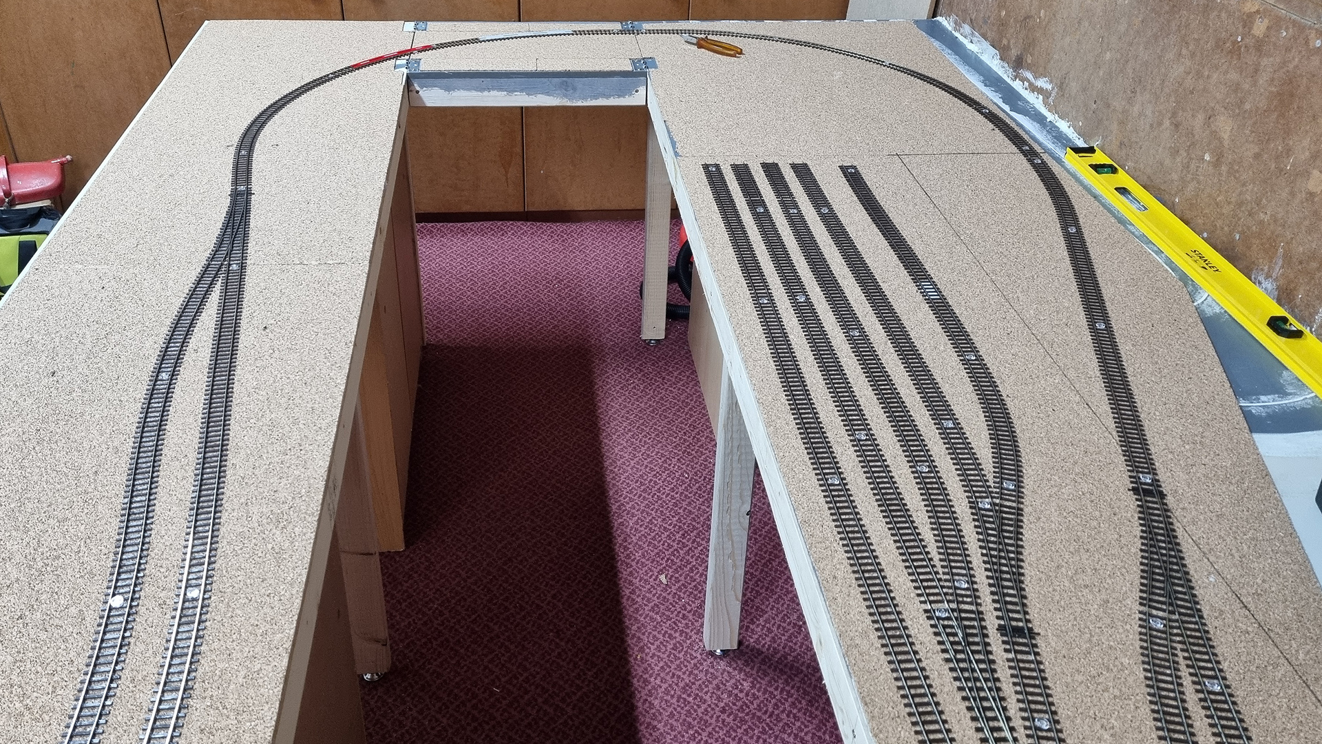
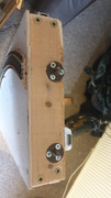
The lift out section, I was going to use the loose pin hinges, to join, but this seemed a bit "clunky" to me, so I have some flight case catches on the way to try instead.
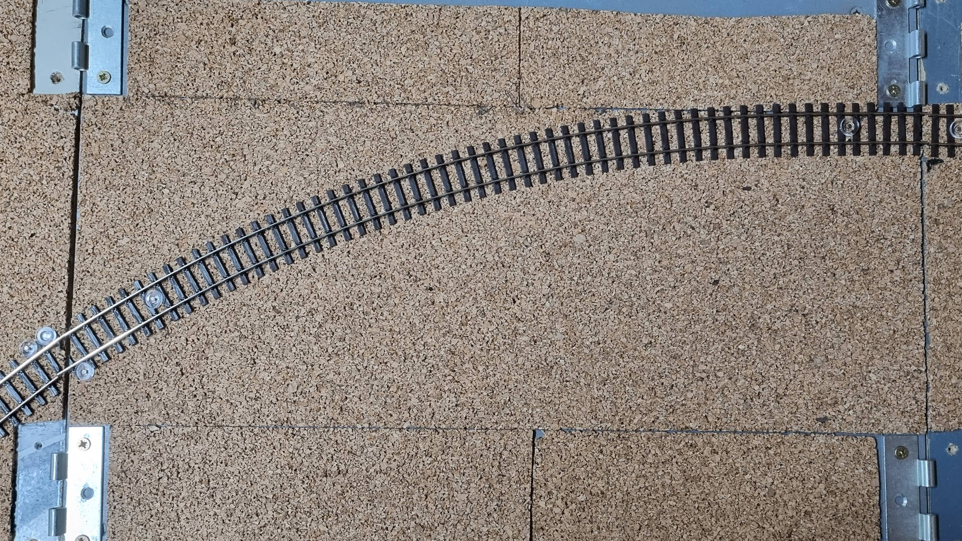
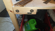
I bought these to help line up the joins, cut back a couple of sleepers and solder the rail to these .. fine on the square join, not sure how they will work out for the angled one !

If anyone has any tips for making the lift out section a smooth trouble free section, I am all ears
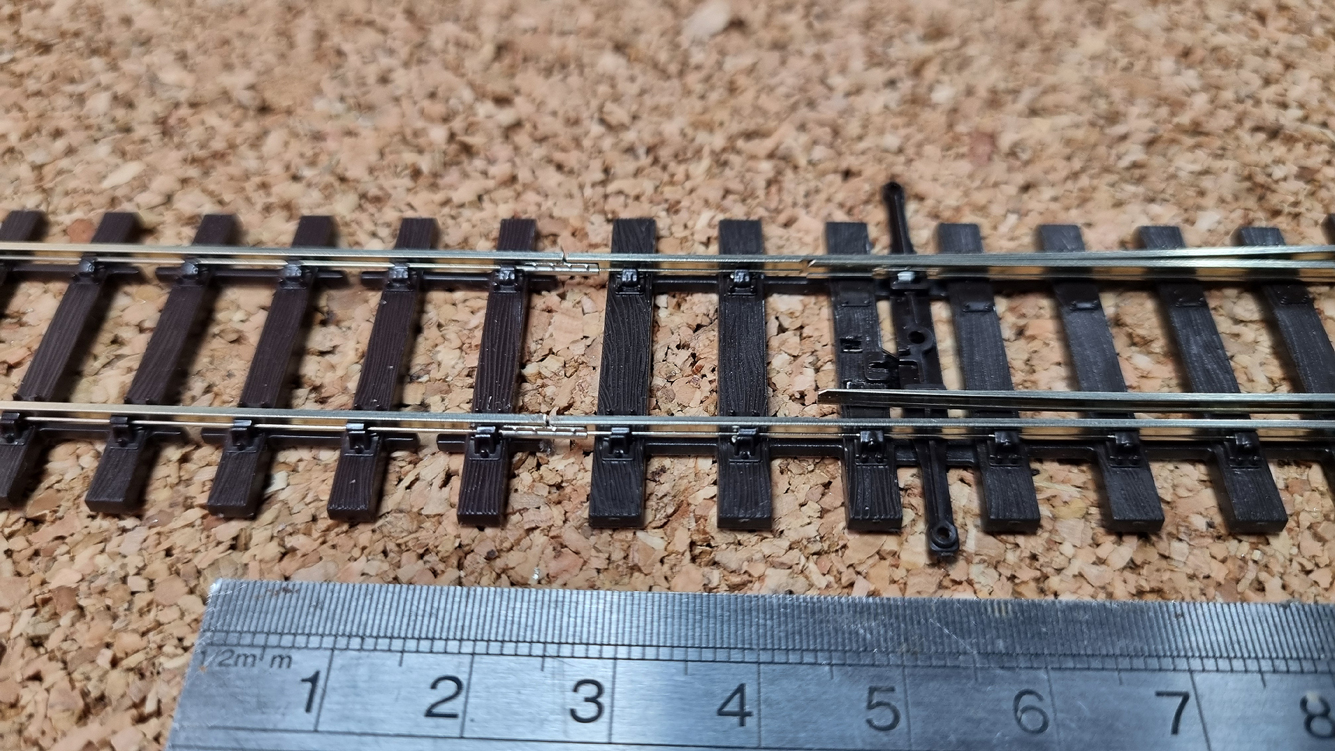
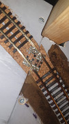
And in the unlikely event someone here here has not seen any of the Peco OO Bullhead track joiners, a gratuitous close up.
I am pleased to say that the minimum radius on the main track is 24" (even most of those have at least a 30" Radius lead in) - in fact only one curve in the shunting area is sub 24" (being 21").
The lift out section, I was going to use the loose pin hinges, to join, but this seemed a bit "clunky" to me, so I have some flight case catches on the way to try instead.
I bought these to help line up the joins, cut back a couple of sleepers and solder the rail to these .. fine on the square join, not sure how they will work out for the angled one !
If anyone has any tips for making the lift out section a smooth trouble free section, I am all ears
And in the unlikely event someone here here has not seen any of the Peco OO Bullhead track joiners, a gratuitous close up.

Re: As yet un-named, my OO layout starts.
Those fishplates look excellent!
I've used a 'home made' version of those alignment tools you've pictured. They help align the rails on a tight curve between the layout and my removable shadow station/fiddle yard.
Peg and Socket Aligners are used to ensure the boards align correctly. The boards are held together when in use with case latches.
I've cut away the sleepers at the ends, and attached two small sections of copper-clad strip-board to the baseboard, on top of the cork underlay. I've then laid the track over the join, gluing and tacking it in place. Once solid, I've soldered the rails to the strip-board... then cut the ends of the rails with xuron railcutters.
It's seemed to work for me!
Father, IT Guy, HO/OO Modeler.
Who is online
Users browsing this forum: No registered users and 2 guests