https://www.soundimports.eu/en/320-617. ... %20-%20DSA%
https://www.eleccircuit.com/the-main-pr ... onverters/
DPDT to control LEDs to show if track is live

Re: DPDT to control LEDs to show if track is live
Very similar to the ones in Brian’s link, I use these. I run a 12v bus pair under the layout and link it to one of these to feed each group of lights. It has the advantage of a display to show input/output values. Of course, you need sufficient amps from the supply to feed all the LEDs.
Quite economical when bought in bulk - I have only three left from the last batch I bought.
https://www.ebay.co.uk/itm/334433225676
Quite economical when bought in bulk - I have only three left from the last batch I bought.
https://www.ebay.co.uk/itm/334433225676
"Not very stable, but incredibly versatile." 

Re: DPDT to control LEDs to show if track is live
Thank you once again for your informative replies.
-
Tricky Dicky
- Posts: 419
- Joined: Fri Oct 05, 2018 6:49 pm
- Contact:
Re: DPDT to control LEDs to show if track is live
Hi Ian, yes your switch wiring is as I described in my earlier post. Yes you will need resistors but they are not for reducing the voltage but instead they are there to limit the current (mA). However, since voltage, current and resistance are all related ie. Ohm’s Law you need to use voltage to make the calculation. Even if your power supply can provide the forward voltage recommended in the data sheet without a suitable resistor an LED will simply continue to draw current beyond its capabilities.IanS wrote: ↑Tue May 31, 2022 7:39 pm
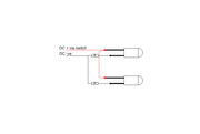
I've not actually installed a 3v PSU but that is to be the source of power to the LED's. (I understand if I use the auxiliary side of an analogue controller with 3v or 5v LED's then resistors will be needed to reduce the voltage.) Red used to represent Positive leg on LED, Black the -ve leg
Have I this right?
I would advise against using a 3V supply simply because the resistor calculations start to get critical when you do not have much overhead voltage wise going a few volts higher with the supply voltage makes things a bit more straightforward.
I provided a quick resistor lookup guide in this post
viewtopic.php?p=31802#p31802
There are suggested resistors for various LEDs at 3V but if you look at the values they tend to be quite low and leave no margin for error.
Richard

Re: DPDT to control LEDs to show if track is live
Hi
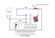
Your drawing in post #8 is incorrect! It will place a full short circuit across the supply with the switch in either position! DO NOT WIRE AS SHOWN IN #8
Wire the LEDs ideally from a 12 volt DC regulated power supply but alternatively you can use a 5 volt former phone charger or even a 9 volt PP3 battery
Wire the switch, LEDs and suitable current limiting series resistors as shown below.
 << Click the Icon to go to my website
-
Tricky Dicky
- Posts: 419
- Joined: Fri Oct 05, 2018 6:49 pm
- Contact:
Re: DPDT to control LEDs to show if track is live
Wow! Brian how did I miss that? Mind you I put it down to a senior moment and replying late at night.Brian wrote: ↑Wed Jun 01, 2022 10:36 am Hi
Your drawing in post #8 is incorrect It will place a full short circuit across the supply with the switch in either position! DO NOT WIRE AS SHOWN IN #8
Wire the LEDs ideally from a 12 volt DC regulated power supply but alternatively you can use a 5 volt former phone charger or even a 9 volt PP3 battery
Wire the switch, LEDs and suitable current limiting series resistors as shown below.
Drawing to be added
Sorry Ian, the correction is scrap the yellow connection between the black line and the switch terminal. Likewise scrap the brown connection between the other black line and other switch terminal. Then connect the red wires from each LED to the terminals, one to each. Finally you need a couple of resistors either in the yellow and brown wires or in the red wires is does not matter which.
Richard
Re: DPDT to control LEDs to show if track is live
I've managed to get this all working with two LED'S however, once again my lack of knowledge is shining through!
How would I wire up, say, 2 red and 2 green so that each show both red and green? (For a point showing route enabled.) (Point a manual switch and insufrog at the moment.) Can I just place them in series or is it more complicated than that?
How would I wire up a bi-colour (in this case red/green) with common cathode to the DPDT switch?
Re: DPDT to control LEDs to show if track is live
Bi Coloured LED Common Cathode wiring to switch.
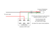
Wiring for Red and Green LEDs that both reds light together and both greens light together, wire each LED Anode (Longer leads) together from the wire form the switch. The add a series resistor to each LED Cathode lead (Shorter lead) and connect the free ends of the resistors together and take that to the supply negative for that colour.
If you want one red and one green to be lit together then do the same as above, but instead of joining two reds join one red Anode and one Green anode together and fit a series resistor in each LED Cathode and then join their free ends together and take to the negative DC supply.
By having separate series resistor per lit LED you can increase Ohm value to dim the induvial LED.
I would not recommend using series wiring of these LEDs especially as they could be of differing colours. Best to use separate resistors.
Just be warned that having a lot of LEDs all lit will often be irritating on the eyes. IMO its far better only to show the actual route set with a single lit LED and the unset route is blank (off). This is what the real railways do and use white LEDs for the set route (I use a single yellow for the set route).
<< Click the Icon to go to my websiteWho is online
Users browsing this forum: No registered users and 2 guests