DPDT to control LEDs to show if track is live

User avatar
IanS
Posts: 940
Joined: Thu Oct 04, 2018 6:19 pm
Location: The Original Washington, UK
Contact:

DPDT to control LEDs to show if track is live

#1

Post by IanS »

Image

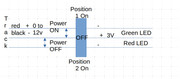
I wish to control the red and green LED's to show if a track is live. The track would be switched 'on' or 'off' via DPDT on-off-on latching switch.

The LEDs would be provided with a separate power feed to the track and would show Green if the switch is 'on' for Power to the track and Red if in the 'off' position for power to the track.

There would be a number of these. Does this wiring setup look correct and/or will it work?

Each switch would be connected to a piece of track between the bus and track, sometimes on the + side and sometimes on the - side (depending on the position I have already installed irj and insul-frog points.

The LED's would be fed in parallel to the switches.

Initially this will all be for analogue power. Eventually the locos will have DCC chips in so the power will be DCC. I accept that turning the power 'off' a track will isolate the loco but that is actually the intention.

I think I've described this correctly and I'm sure someone will tell me if I'm wrong! :D
Does all this seem feasible and possible?
Tricky Dicky
Posts: 419
Joined: Fri Oct 05, 2018 6:49 pm
Contact:

Re: DPDT to control LEDs to show if track is live

#2

Post by Tricky Dicky »

Ian if I have read this correctly you have a bus set up on a DC layout and you want to be able to switch an isolated section of track ON/OFF and have two LEDs to indicate when the track is ON or OFF.

Under normal circumstances to switch a section of track would only require a single pole, single throw switch (SPST) and this could be wired in as you say either feed to the track.

However, if you want the switch to do other things at the same time then you will require a double pole, double throw (DPDT) switch, you do not need a centre off switch just a standard DPDT.

On a DPDT switch you will find 6 terminals in two rows of three, each row of three is in fact a Single pole, double throw (SPDT) switch that work in tandem. For the track switching you simply want to use one switch as a simple ON/OFF and to do this simply wire your feed from the bus to the centre terminal and the feed to the track from one of the outer terminals. Which outer terminal will be your choice as to wether the track is ON with the toggle either up or down.

For the indicator LEDs you are going to use the other SPDT switch as a changeover switch directing the current in, out of either terminal. Again wire your (+) LED supply to the centre terminal of the second SPDT switch in the DPDT switch. Connect your respective LEDs and series current limiting resistors to the outer terminals observing correct polarity and back to the (-) of your LED power supply. Flicking the toggle will now direct the current through either LED depending on the position of the toggle. If the wrong colour LED emits light when either the track is live or not, simply swap the outer terminals on the LED side of the DPDT switch.

Richard
Tricky Dicky
Posts: 419
Joined: Fri Oct 05, 2018 6:49 pm
Contact:

Re: DPDT to control LEDs to show if track is live

#3

Post by Tricky Dicky »

IanS wrote: Thu May 19, 2022 9:39 pm Image


Initially this will all be for analogue power. Eventually the locos will have DCC chips in so the power will be DCC. I accept that turning the power 'off' a track will isolate the loco but that is actually the intention.
Hi again. I forgot to address this comment in my previous post. With DCC there is no need for switchable sections. Although the rails are permanently powered locos will not move until their decoders are addressed by the controller and signals sent instructing the loco. Without the decoder being addressed a loco will happily sit on powered rails waiting for instruction.

Richard
User avatar
IanS
Posts: 940
Joined: Thu Oct 04, 2018 6:19 pm
Location: The Original Washington, UK
Contact:

Re: DPDT to control LEDs to show if track is live

#4

Post by IanS »

Thank you for your comments. Your understanding of my intentions are correct.

For DCC my understanding is that their is a power draw for idle locos and as I hope to have quite a few on the layout sitting 'parked' (aka in storage) the intention is to limit the draw by switching the power off for that section.
Tricky Dicky
Posts: 419
Joined: Fri Oct 05, 2018 6:49 pm
Contact:

Re: DPDT to control LEDs to show if track is live

#5

Post by Tricky Dicky »

I have not looked into current draw as my Lenz 100 is capable of 4A and I do not have that many locos. I imagine that a bog standard decoder would only require a few milliamperes whilst a sound decoder would be a lot more. I suspect even with say three trains running there would be plenty of overhead for others standing idle. Perhaps Brian or someone more in the know might be able to put some figures to the above. Of course if you do have a lot of locos standing around then splitting the layout up and using a booster would ensure there was enough current available but of course there is a cost implication.

Richard
User avatar
Brian
Posts: 2298
Joined: Thu Oct 04, 2018 3:49 pm
Location: SE Kent
Contact:

Re: DPDT to control LEDs to show if track is live

#6

Post by Brian »

Hi

Several years ago I conducted some basic rule of thumb current readings using the Gaugemaster Prodigy Advance 2 DCC system. I can't find the data to hand right away, but from memory, the quiescent current of a decoder (Non sound) was less then 0.01Amp - less than 10 milliamps. Thats with everything turned Off - No lights On etc. Average running current for a non sound modern loco running light was around 250ma while a sound fitted loco came in at around 350 to 400ma. Of course track rail voltage will also cause minor current alteration.

Basically, the standing (Quiescent) current was so low it wasn't worth considering as 100 locos just sitting on the rails doing nothing would draw less than 1.0Amp on a PA2 outputting a possible 3.5Amps at 15volts. The decoder is not doing anything other than listening to the data signals being sent. :D
Image << Click the Icon to go to my website
User avatar
IanS
Posts: 940
Joined: Thu Oct 04, 2018 6:19 pm
Location: The Original Washington, UK
Contact:

Re: DPDT to control LEDs to show if track is live

#7

Post by IanS »

Thank you for the reply Brian. Most informative.
User avatar
IanS
Posts: 940
Joined: Thu Oct 04, 2018 6:19 pm
Location: The Original Washington, UK
Contact:

Re: DPDT to control LEDs to show if track is live

#8

Post by IanS »

Tricky Dicky wrote: Fri May 20, 2022 6:52 am
For the indicator LEDs you are going to use the other SPDT switch as a changeover switch directing the current in, out of either terminal. Again wire your (+) LED supply to the centre terminal of the second SPDT switch in the DPDT switch. Connect your respective LEDs and series current limiting resistors to the outer terminals observing correct polarity and back to the (-) of your LED power supply. Flicking the toggle will now direct the current through either LED depending on the position of the toggle. If the wrong colour LED emits light when either the track is live or not, simply swap the outer terminals on the LED side of the DPDT switch.

Richard
I think I have understood you!

I've attached a picture (worth 10000 of my words!) that may help explain what I've wired up.

I've not actually installed a 3v PSU but that is to be the source of power to the LED's. (I understand if I use the auxiliary side of an analogue controller with 3v or 5v LED's then resistors will be needed to reduce the voltage.) Red used to represent Positive leg on LED, Black the -ve leg

Have I this right?
User avatar
Steve M
Posts: 3641
Joined: Thu Oct 04, 2018 5:29 pm
Location: Rochester, Kent
Contact:

Re: DPDT to control LEDs to show if track is live

#9

Post by Steve M »

Looks fine to me (I’m not an electrician :? ) but fit a suitable resistor regardless of the power supply. It will act as a protector in case of an accidental over supply and it will dim the LED slightly - an unregistered LED will be seriously bright.
In my control panel I have resistors on each LED and pass the 12v supply through a DC/DC buck which I can vary down to the point at which the LEDs just turn on.
Last edited by Steve M on Wed Jun 01, 2022 1:00 pm, edited 1 time in total.
"Not very stable, but incredibly versatile." ;)
User avatar
IanS
Posts: 940
Joined: Thu Oct 04, 2018 6:19 pm
Location: The Original Washington, UK
Contact:

Re: DPDT to control LEDs to show if track is live

#10

Post by IanS »

What's a DC/DC buck?
Post Reply

Who is online

Users browsing this forum: No registered users and 2 guests